


For the lower bands I am using a 40/80 m trap dipole. In order to become qrv on 30 m, I added a radiation coupled lambda/2 element for 30 m, using 10 cm spreader. After cutting the additional wire to the right length, the resonance on 30 m is exactly at 10.1 MHz. The additional element has no influence on the resonance for 40 and 80 m, but the impedance on 30 m is with 150 Ohm significant higher than 50 Ohm.


My spider beam is up for one year now in Tagaytay. Unfortunately we have a lot of wind here, and the element wires of the beam started tangling.
I can only get it down in March or April, to check and bring some more tension to the lines and wires.
As the propagation conditions getting worse for 15 m and 17 m, I extended my linear loaded dipole on both sides by 1.8 m in order to cover the 20 m band. SWR is ok without modification of the 1 : 4 transformation line.

 Will see, how it works in the upcoming CQWW DX CW contest.
After replacement of my 80/40 m trap dipole with the G5RV antenna, I made some measurements. The antenna has a height of 12 m at the center, and is hanging as an inverted V with both ends still 4 to 5 meter above ground. The symmetric feeder line is connected via a 1:1 balun to 12.9 m 50 Ohm coaxial cable.
In Singapore space is limited, and in our appartment it is difficult to setup any HF antenna. Our balcony is the only place where I have a space to mount something. Even there, officially nothing is allowed to extend out from the building.
I decided to setup a simple vertical, using a telescopic fiberglass pole, which I can pull out temporarly, when it is getting dark. The pole has a total length of 10 m, approx. 1 m (the lowest segment) safely mounted to the balcony railing and sidewall.
Continue reading Fiberglass Balcony Stealth Antenna for 40 m
Installation of my 12 m tower and shortwave beam.
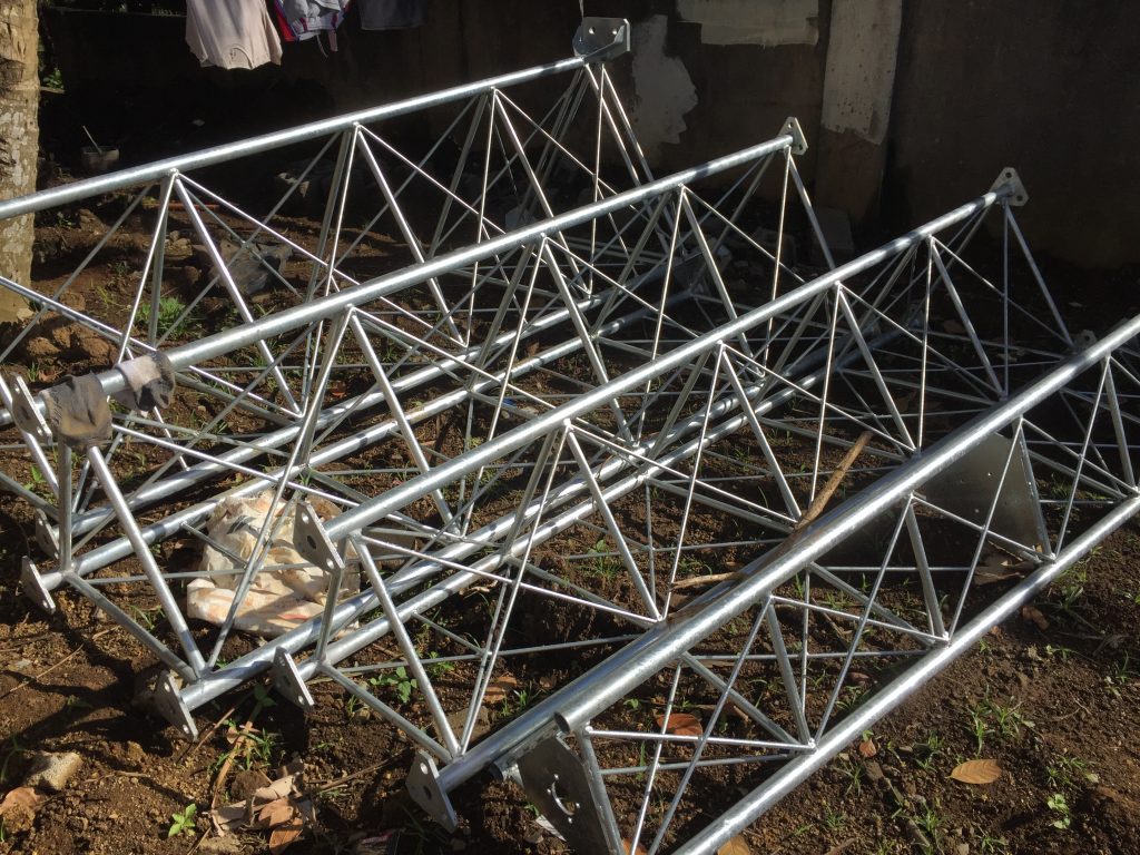 4 segments 3 m each
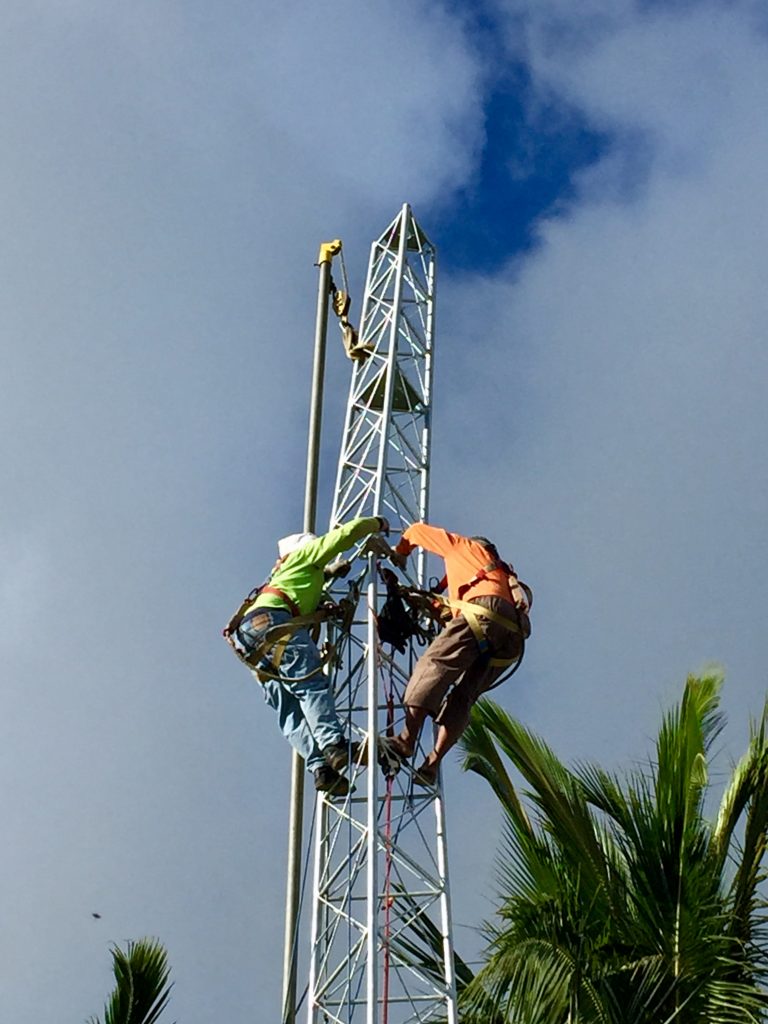 The last segment put in place
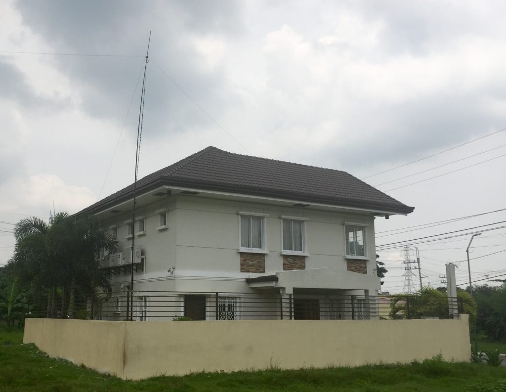
This time we stay longer than a week in our second home, and I set up a 12 m fibreglass pole with a G5RV multi-band dipole antenna for 40 m to 10 m. The pole is located at on corner of our area, the dipole endings are fixed at two other corners, so the antenna has a form of a 90 degree inverted vee.
For my amateur radio activities on the HF bands I only have a 3.6 m wide balcony available for antennas. After some study I decided to experiment with a shortened dipole for the 15 m band. The full size 21 MHz half wave dipole would require a span of approx 7 m, therefore I searched for a solution to shorten the full size length by 50 percent.
Finally I decided for a linear loaded dipole; the layout and resulting dimensions are shown below.
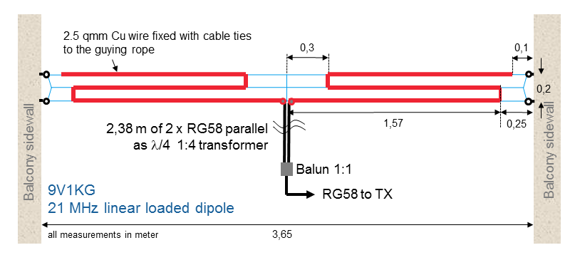
First measurements at the resonance frequency showed a low input impedance at the dipole’s feed point with values around 10 Ohm. The theoretical radiation resistance of a 2 x 1.6 m short dipole would be 10 Ohm, so it is an indication of low losses in the system. In order to match the antenna to the 50 Ohm of the transceiver, I use a quarter wave transmission line transformer consisting of two parallel connected 50 Ohm coaxial cables.
After fine tuning the length of the antenna wires, I achieved an SWR below 1.5 for the CW segment of the 15 m band.
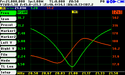
The antenna’s bandwidth is around 200 kHz; I could already work DX stations around the world.
Dipole feed point and 1:1 balun


