For my amateur radio activities on the HF bands I only have a 3.6 m wide balcony available for antennas. After some study I decided to experiment with a shortened dipole for the 15 m band. The full size 21 MHz half wave dipole would require a span of approx 7 m, therefore I searched for a solution to shorten the full size length by 50 percent.
Finally I decided for a linear loaded dipole; the layout and resulting dimensions are shown below.
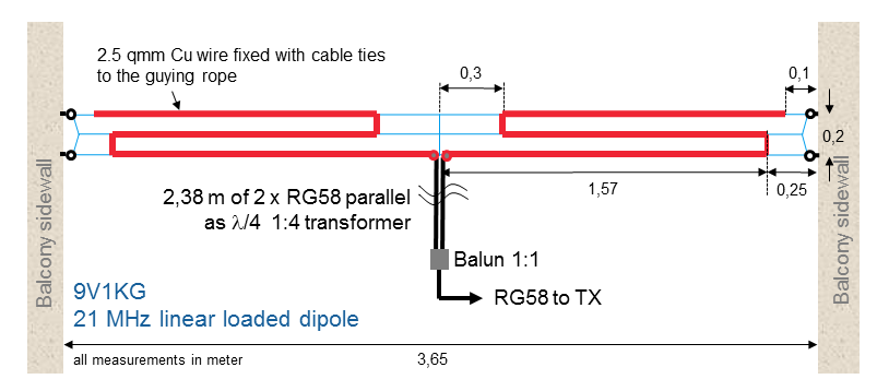
First measurements at the resonance frequency showed a low input impedance at the dipole’s feed point with values around 10 Ohm. The theoretical radiation resistance of a 2 x 1.6 m short dipole would be 10 Ohm, so it is an indication of low losses in the system. In order to match the antenna to the 50 Ohm of the transceiver, I use a quarter wave transmission line transformer consisting of two parallel connected 50 Ohm coaxial cables.
After fine tuning the length of the antenna wires, I achieved an SWR below 1.5 for the CW segment of the 15 m band.
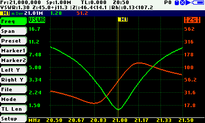
The antenna’s bandwidth is around 200 kHz; I could already work DX stations around the world.


Dipole feed point and 1:1 balun


 Will see, how it works in the upcoming CQWW DX CW contest.
