After many years using an active loop antenna with the Cross Country Wireless Loop amplifier for my SDR, I upgraded to the LZ1AQ active loop amplifier AAC-1C.
I replaced the former single loop wire – made of stainless steel – with two parallel loops using AWG10 (2.6 mm) copper wire. The loop diameter is 70 cm and the distance between both loops is 44.5 mm.


As a holder I use a 1600 x 35.5 mm PVC tube (marked as 32 mm UPVC pipe) and added a 710 x 21.5 mm PVC tube (marked as 15 mm UPVC pipe) to support the loop. All additional parts are 3D printed in PETG. Besides the end caps and loop holder the wires are additional supported using four spreaders.
As before, the loop is mounted horizontal outside the apartment window in the 17th floor. In connection with my SDR the usable frequency range is 20 kHz to 55 MHz.


 Will see, how it works in the upcoming CQWW DX CW contest.

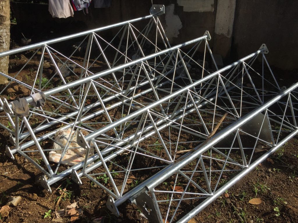 4 segments 3 m each
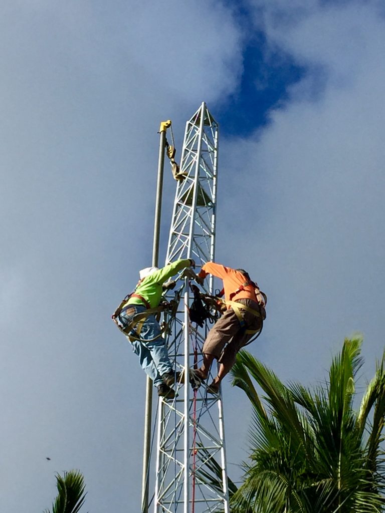 The last segment put in place